

This offer ends in:
- Stock: 23
23 - Brand: Generic
- Reward Points:
- Model: LC-LM358-PWM2V
- Weight: 15.00g
- pkg: 9.00cm x 7.00cm x 2.00cm
- SKU: YXK573
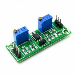
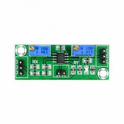
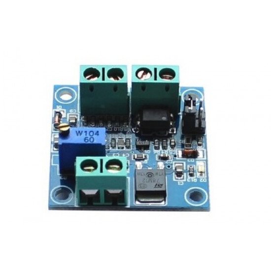
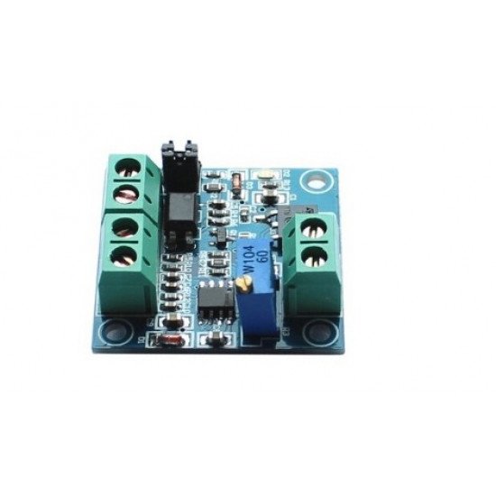
LC PWM turn voltage module LC-LM358-PWM2V can convert PWM digital signal into 0 to 10 v analog signals.Can be used in the PLC or other industrial panel switch signal interface.By adjusting the PWM duty ratios to adjust output voltage.Module size is small, easy to apply in different places
Most likely application for a Maker would be controlling speed of CNC spindle, but can be used for other control or signal interface switching.
>MCU embedded technology.
Easy to operate, can pass to fine-tuning potentiometer.
Through the short circuit choose PWM signal input level range.
Module is small, portable and easy to use.
Technical parameters:
Module working voltage: DC 12 v - 30 v.(power requirement: more than 100 mA)
PWM signal receiving frequency range: 1 KHZ - 3 KHZ;
PWM signal input level range:
Fengfeng value of 4.5 V to 10 V level, jump needle at 5 V.The class
level signal mainly for conventional industrial control CARDS (e.g.,
MACH3 boards), 5 v CPU interface;
Fengfeng value between 12 and 24 v level, jump needle at 24 v.The class level signal mainly for conventional PLC interface.
PWM conversion range: 0% - 100% PWM conversion 0 to 10 v
Permissible error: 5%.
3, Introductions
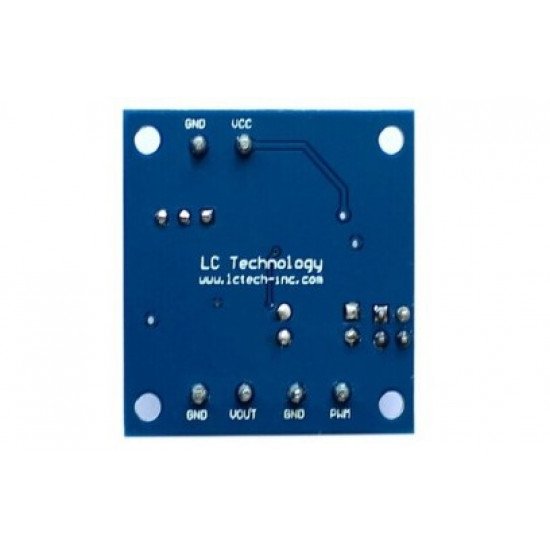
VCC: work power 12 v - 30 v.
GND: working power。
PWM: input PWM signal positive pole.
GND: the input signal is negative end.
VOUT: 0 to 10 v output voltage.
GND: output voltage.
Instructions: after power on, there is no input signal, the output is 0
v.Electricity for the first time, it's best to do a calibration
debugging: find a 50% duty cycle of the access to the PWM signal, GND,
corresponding to the relative amplitude jump needle.Frequency in the 1
KHZ - 3 KHZ, VOUT is measured with a multimeter, GND two ports, the
table displays at around 5 v, adjust the potentiometer on the board,
make says in 5.00 v on the multimeter. The calibration is your pulse
signal and the corresponding relation of the module.When the frequency
changes, there may be offset, the corresponding relationship needs to be
calibrated.
Output voltage can be adjusted by adjusting the duty ratios.
Precision could be controlled by adjusting the potentiometer.

